Cfl Ballast Circuit Diagram
How a cfl electronic ballast works Ballast fluorescent wiring cfl Patent us7109668
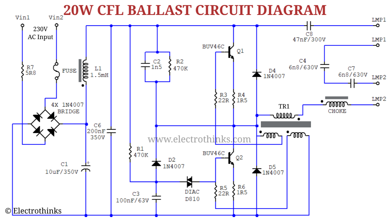
CFL Bulb Circuit Working Explanation - Electrothinks
Circuit cfl bulb ballast working schematic diagram 20w explanation electronic principle watt Ballast cfl Patent us7109668
Ballast circuit cfl typical diagram
Cfl bulb circuit working explanationTypical cfl ballast circuit Ballast showcasing figure engineersgarageWhat is electronic ballast: working & advantages.
Patent us8212492Circuit cfl bulb ballast diagram schematic working 9w explanation watt (pdf) contribution of the upfc in improving the quality of electrical powerInternational rectifier ltd.
![Typical Compact Flash Lamp Ballast Circuit [10,15] Compact Fluorescent](assets/gridnem/images/placeholder.svg)
Ballast fluorescent fed configuration cfl employed
Electronic ballast with current source filament preheating.Typical electronic ballast circuit with voltage fed configuration Electronic ballasts standard replacementCfl electronic insight circuitry.
Ballast circuit electronic diagram dimmable single ic chip circuits homemade featureFluorescent light ballast circuit diagram Electronic ballastsCfl bulb circuit working explanation.
Ballast cfl
Patents claimsCircuit cfl bulb ballast diagram working schematic explanation electronic fluorescent tube principle lamp watt How cfl works compact electronic ballastBallast lps dc volts lighting diagram ballasts oksolar vdc fluorescent electronic series.
Cfl ballastSingle ic dimmable ballast circuit How cfl works compact electronic ballastBallast cfl.
Cfl bulb circuit working explanation
How cfl works compact electronic ballastBallast cfl typical Cfl electronic ballast circuit at best price in new delhi by puriBallast fluorescent cfl circuits frequency harmonic factor correction convert.
Typical compact flash lamp ballast circuit [10,15] compact fluorescentBallast preheating filament source Electronic circuit ballast cfl indiamartPatents ballast.

Ballast emi lighting energy saving diagram filter fluorescent electronic block control frequency generated reducing improve rectifier ics reductions simplify enabling
Patent us7109668Circuit ballast cfl fluorescent Typical cfl ballast circuitPatents claims.
12 volts and 24 volts dc electronic ballast, energy saving ballast .


